GameBoy Printer Hacking with Elixir
Table Of Contents
A GameBoy Printer?
Some time ago, I purchased a GameBoy Printer on eBay. I was curious about how it worked and wanted to make it print images from a Raspberry Pi. This accessory, with limited game support, uses 38 mm thermal paper, has a 160-pixel horizontal resolution, practically unlimited vertical resolution, and prints in three shades of gray.
The images printed are super lo-fi, but it is a fun piece of gaming history. Back in the day, you could print Pokédex entries, photos from the Link’s Awakening DX photo album, Pokémon trading cards, certificates for high scores in certain games, and a few other things. Most applications were very gimmicky. The printer is also slow and the paper in the correct size is somewhat expensive and hard to find. What is probably the coolest use of the printer is the GameBoy Camera. The GameBoy Camera is a game cartridge that contains a rotatable camera and photo editing software. It has a bunch of fun features and you can print the photos you take with the camera. Some of its features where very impressive for the time, like taking panorama photos or taking selfies by rotating the camera to point towards you and of course the ability to print the photos you took. All you needed was a GameBoy Printer and a whopping 6 AA batteries to power the printer.
The camera is what initially got me interested in the printer, so maybe I’ll try to do something with the camera in the future. This post is about the printer though.
Hooking it up to the Raspberry Pi
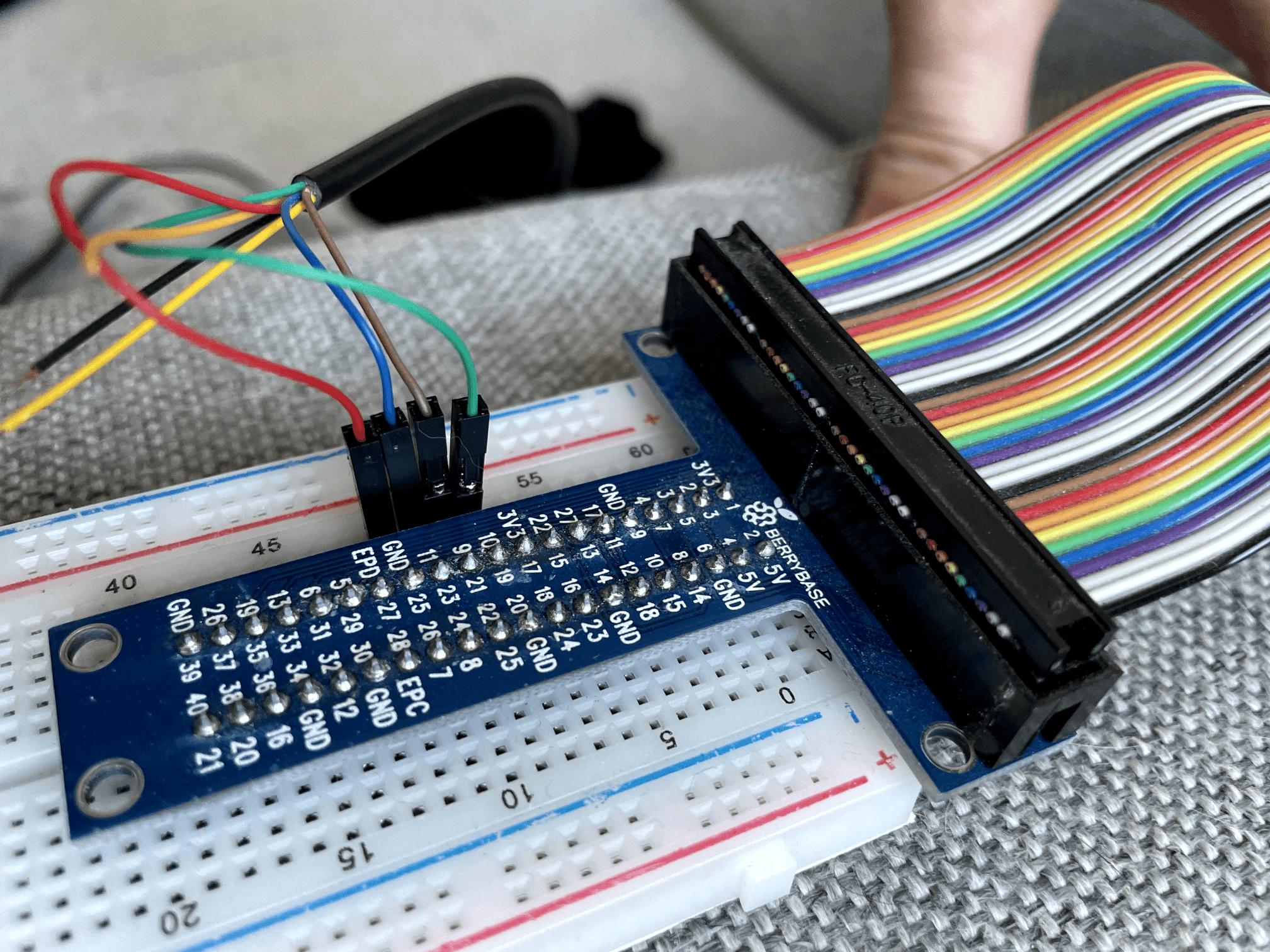
The printer connects to the GameBoy via a link cable, which is the same cable you use to connect multiple GameBoys to play multiplayer games. I cut a link cable in half and added dupont connectors to the ends. I then connected the printer to the Raspberry Pi using the link cable and a T-Cobbler on a bread board.
Figuring out the pinout of the link cable was a bit tricky. I found a couple of different pinouts online, and the pinout I found that worked was the following:
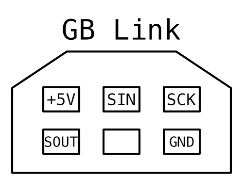
Out of the 6 six pins, only 5 are used.
- Pin 1: +5V
- Pin 2: Serial Data Out
- Pin 3: Serial Data In
- Pin 4: Unused
- Pin 5: Serial Clock
- Pin 6: Ground
Implementing the protocol
The communication between the GameBoy and the printer is a very simple SPI based protocol. The protocol has already been reverse engineered and documented, so I didn’t have to do that myself. The protocol allows you to send image data to the printer, print the buffered image data, and retrieve the device status (jam, battery, etc.).
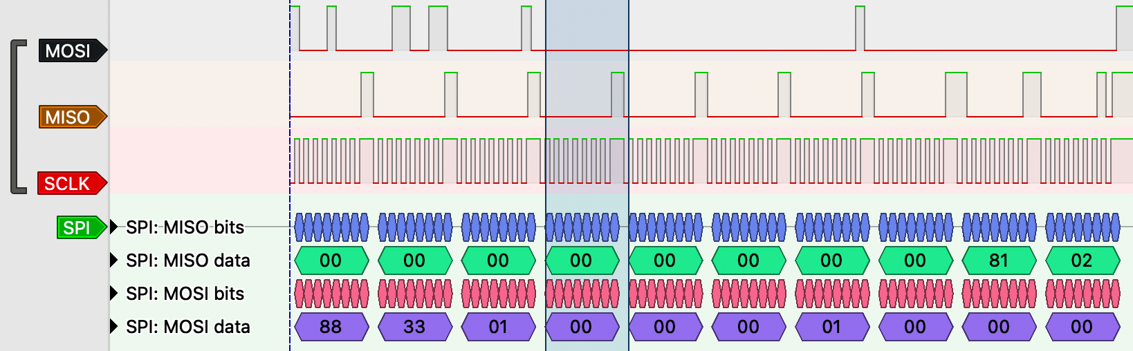
I used the circuits_spi library to communicate with the printer. The library has a NIF that wraps the Linux SPI API. Getting the SPI clock speed, delay and mode right was crucial so I used a logic analyzer to compare my implementation of the protocol against the communication from an actual GameBoy to the printer.
The parameters I found to work were:
- Speed: 8192 Hz
- Delay: 120 µs
- Mode: 3
Opening the device using the circuits_spi is simple, it requires the device name and the configuration parameters. The device name can be found by calling Circuits.SPI.bus_names().
{:ok, spi} = SPI.open("spidev0.0", speed_hz: 8192, mode: 3, delay_us: 120)The first command that should be sent to the printer is the initialization command. This will clear the printer’s buffer. Sending the command is done by calling SPI.transfer/2 with the SPI device and the data to send.
{:ok, response} = SPI.transfer(state.spi, message(:initialize))
<<_::binary-size(9), alive, status>> = response,
%Status{online: true} = status = Status.parse(alive, status)
The message/2 function takes a command atom and an optional payload and creates a binary that can be sent to the printer. It concatenates the corresponding command byte with the payload and calculates the checksum.
@magic <<0x88, 0x33>>

defp message(command, data \\ <<0x00>>) do
  command =
    case command do
      :initialize -> <<0x01>>
      :print -> <<0x02>>
      :data -> <<0x04>>
      :read_status -> <<0x0F>>
    end

  header = <<command::binary, 0x00, byte_size(data)::16-little>>
  checksum = <<byte_sum(header <> data)::16-little>>

  @magic <> header <> data <> checksum <> <<0x00, 0x00>>
end

defp byte_sum(data) do
  data |> :binary.bin_to_list() |> Enum.sum()
end
Status is a small convinience module that parses the response from the printer. It checks whether the alive byte is 0x81 and translates the status byte to a struct with fields like :online, :checksum_error, :printing and so on.
Image encoding
Before we can send any images to printer we need to convert them to correct format. The format is the GameBoy’s tile format, the very same format that games use to encode image data. This has the benefit that games can use the same data displaying images on the screen as sending images to the printer. One tile is 8x8 pixels and takes up 16 bytes. Each row of the tile is represented by two consecutive bytes and each bit position in the byte pairs are combined to give a 2-bit value that represents the color of the pixel in that x position.
You can fiddle with this interactive tile editor to get a feel for the tile format.
Assuming with start with a RGB bitmap we first have to convert it to grayscale.
# convert the binary to a list a list of RGB values
rgb =
  image_data
  |> :binary.bin_to_list()
  |> Enum.chunk_every(3)

# convert the rgb values by averaging the color channels
grayscale =
  rgb
  |> Enum.map(fn [r, g, b] -> div(r + g + b, 3) end)
Now that we have grayscale data need to convert it to 2 bits per pixel. Instead of naively quantizing the pixels to 4 levels, we can use a technique called ordered dithering using a Bayer matrix to reduce the color depth while minimizing visual artifacts.
I won’t go over how exactly this works but the gist is that we use a matrix of offsets to distribute the error of quantization across neighboring pixels. The implementation below will give us an image of where each pixel is either 0, 1, 2, or 3.
offsets = [{1, 0}, {-1, 1}, {0, 1}, {1, 1}]
factors = [7 / 16, 3 / 16, 5 / 16, 1 / 16]

factors = offsets |> Enum.zip(factors)

quantize = fn pixel, levels ->
  round(Float.round(pixel / 255 * (levels - 1)) * (255 / (levels - 1)))
end

dither = fn data, w, h ->
  data = :array.from_list(data)

  data =
    for y <- 0..(h - 1), x <- 0..(w - 1), reduce: data do
      data ->
        idx = y * w + h
        old = :array.get(idx, data)
        new = quantize.(old, n)
        data = :array.set(idx, new, data)

        err = old - new

        data =
          if x < w - 1 do
            idx = idx + 1
            value = :array.get(idx, data)
            :array.set(idx, round(value + err * 7 / 16), data)
          else
            data
          end

        data =
          if x < w - 1 do
            idx = idx + 1
            value = :array.get(idx, data)
            :array.set(idx, round(value + err * 7 / 16), data)
          else
            data
          end

        data
    end

  :array.to_list(data)
end
Finally we can convert the dithered image to tiles. First we reorder the image data so that the values making up the individual tiles are consecutive.
width = 160
height = 140

tile_size = 8
tiles_per_row = div(width, tile_size)

dithered = dither.(grayscale)

tiles =
  dithered |> Enum.chunk_every(tiles_per_row * tile_size * tile_size)
  |> Enum.flat_map(fn row ->
    tile_rows = row |> Enum.chunk_every(8)

    Enum.map(0..(tiles_per_row - 1), fn offset ->
      tile_rows |> Enum.drop(offset) |> Enum.take_every(tiles_per_row)
    end)
  end)
And then we encode the pixel values into bytes in the tile format.
import Bitwise

tile_bytes =
  tiles
  |> Enum.map(fn rows ->
    Enum.map(rows, fn row ->
      row
      |> Enum.with_index()
      |> Enum.reduce([0, 0], fn {pixel, i}, [lo, hi] ->
        case pixel do
          0 -> [lo, hi]
          1 -> [lo ||| 1 <<< (7 - i), hi]
          2 -> [lo, hi ||| 1 <<< (7 - i)]
          3 -> [lo ||| 1 <<< (7 - i), hi ||| 1 <<< (7 - i)]
        end
      end)
    end)
end)IO.iodata_to_binary(tile_bytes) will now give us a binary that we can send to the printer.
Sending Image Data
Now that we have a way to convert arbitrary images to the tile format we can send it to the printer. Once the printer has been initialized the image data can be sent to the printer. The printer has a buffer that can hold 5760 bytes which is 160x144 pixels at 2 bits per pixel. Only 160x16 pixels (640 bytes) can be sent at a time. That means a full 160x144 image will have to be sent in 9 chunks. The printer expects an empty chunk to be sent after the last chunk of image data.
data
|> :binary.bin_to_list()
|> Enum.chunk_every(640)
|> Enum.map(&:binary.list_to_bin/1)
|> Enum.each(fn chunk ->
  msg = message(:data, chunk)
  {:ok, _} = SPI.transfer(spi, msg)
end)

{:ok, _} = SPI.transfer(spi, message(:data, <<>>))
Printing the Image
Now for the fun part! After the sending the image data to the printer the :print command can be sent to the printer. This will make the printer print the buffered image data. This command expects a 4 byte payload that specifies the top and bottom margin, the palette and the intensity. The first byte of the payload is always 0x01.
import Bitwise

margin_top = 0x2
margin_bottom = 0x2
margin = margin_top <<< 4 ||| margin_bottom

palette = 0xE4
intensity = 0x40

payload = <<0x01, margin, palette, intensity>>

{:ok, _} = SPI.transfer(state.spi, message(:print, payload))
If everything went well the printer should start printing the image. The printer is slow and it takes a few seconds to print a full image.
Conclusion
Connecting the GameBoy Printer to a Raspberry Pi opened up possibilities beyond what Nintendo originally intended. Using Elixir and Nerves provided a solid foundation for hardware communication, with pattern matching and binary manipulation making protocol implementation straightforward.
The most satisfying part of this project was watching that first image emerge from this ancient device. While the GameBoy Printer may be limited by today’s standards, its constraints inspire creativity - working within the 2-bit color palette forces you to reduce images to their essential elements.
I’m currently thinking of expanding this project into a networked printer that can be used via the line printer daemon (LPD) protocol. This would allow for seamless integration with operating systems that support LPD, enabling users to print images directly from their computers or mobile devices. Implementing the LPD protocol will be trivial, but what will challenging is ingesting the print data and turning it into the the correct format for the GameBoy Printer. Sounds like a good excuse to write a PostScript interpreter in Elixir…
I hope you’ve enjoyed reading about my little adventure with the GameBoy Printer. Stay tuned for updates on the networked printer project!